How to setup an external device to a Sensor of a ProConnect NVR
To physically set up a Sensor on a ProConnect Recorder:
- Insert the positive side of the sensor in pin 1, 2, 3 or 4 by depressing the orange button with a small flat-head screw driver.
- Insert the ground in one of the relay ground pins.
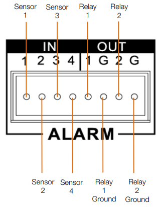
Note: When connecting a sensor to the sensor relay block, use grounds on the relay side (Relay 1 Ground or Relay 2 Ground) as the sensor ground. Terminals on the sensor side will not provide a ground.
3. Log on to the recorder and go to Setup>Sensors.
4. Enable a specific sensor by checking the box in the Enable column.
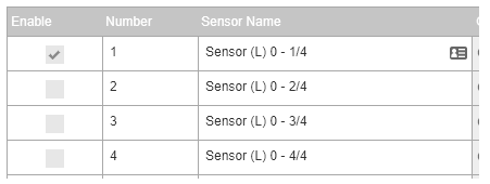
5. Modify the Recorder sensor number in the Sensor Number column if wanted.
6. To modify the sensor name, type the new name into the Sensor Name box.
7. Set Normally Open or Normally Closed in the Type (NO/NC) drop down.
8. If the Sensor is giving false positives, you can change the debounce time to ignore repeated contacts.
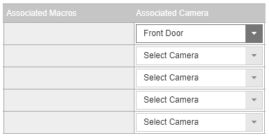
9. Associate a camera to record with the sensor by selecting a camera from the Associate Camera drop down.
10. Modify the image offset value if a delay is required when recording a sensor event.
11. Check the box labeled Invert State if desired.
12. Click Save.
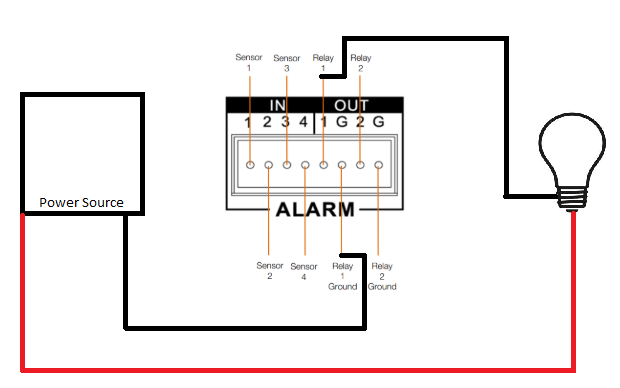
To use relays to add a alarm light or siren device to your ProConnect recorder:
1. Get a 12v power supply
2. Run the positive of the power supply to the positive of the light/siren
3. Run the ground of the power supply to the ground of the ground pin of the relay then run.
4. Then run the relay pin 1 or 2 to the positive of the light/siren.
5. Modify the relay number if needed by click in the Relay Number field and hitting backspace until cleared and type in the new number.
6. Modify the relay name by selecting Relay Name field and hitting backspace until cleared and type in the new relay name.
7. Set Normally Open or Normally Closed in the Type (NO/NC) drop down.
8. Modify the Duration if the momentary activation time needs to be modified. Click Save.
Max safe voltage is 30 vdc / 1 amp for the internal relay.
- Warning: 3rd party hardware in the rest of the circuit may have different requirements.
- Warning: Do not exceed the limitations of the relay for max current or voltage values.
Pro Tip:
- The relay names when configuring the relay (Relay (L) 0 - 1/2 and Relay (L) 0 - 2/2) refer to the specific relay pinned/used on the back. 1/2 referring to pin number 1 and 2/2 referring to pin number 2.